Week 15: Wildcard Week
What should I do this week?
In this fifteeth week of Fab Academy, the goal is to design and produce something with a digital fabrication process (incorporating computer-aided design and manufacturing) not covered in another assignment, documenting the requirements that your assignment meets, and including everything necessary to reproduce it.
Further learnings are listed below:
- Demonstrate workflows used in the chosen process.
- Try out new machines and processess
- Explain the mistakes that I had made and how I corrected it
- Include hero shots of the product
- Try out a cool experiments
The following are the softwares that I have used for learning various operations:
- Fusion 360 : Designing
- Cura : Slicing
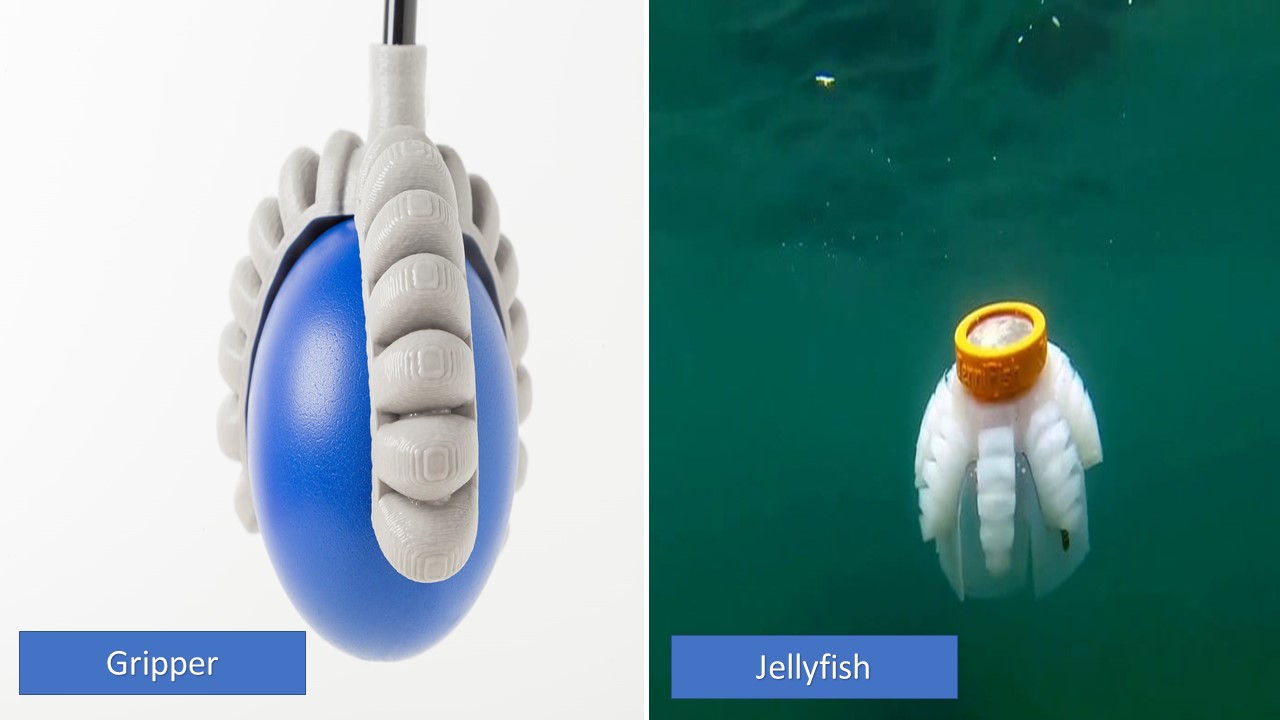
For this cool week, I am going to try my hands on soft robotics. I was never interested in robotics but when it comes to the application of soft robotics, I must say I am amazed. My idea is to design a soft robotic jelly fish which I was inspired by the work of Jono Sanders. I am pretty sure that it won't work as expected but anyway I am planning to make my hands dirty! If the jelly fish idea doesn't work, I have a Plan B, i.e. I will make a soft robotic gripper and try to make it work.
References
Week 15: Action Plan
| |
|
|---|---|
| Wednesday | Prof. Neil's class on Wildcard Week |
| Thursday | Designing the mould |
| Friday | Reseach about various composites |
| Saturday | Documentation |
| Sunday | Documentation |
| Monday | Soft Robotics |
| Tuesday | Documentation |
My intital plan was to create a soft-robotic gripper for this week, but then I though that I need to do something interesting. The jellyfish is kind of cool animal to biomimic and I think it would be great experiment.
What are Soft Robots?
Soft robotics is the specific sub-field of robotics dealing with constructing robots from highly compliant materials, similar to those found in living organisms. In contrast to robots built from rigid materials, soft robots allow for increased flexibility and adaptability for accomplishing tasks, as well as improved safety when working around humans.These characteristics allow for its potential use in the fields of medicine and manufacturing. Bio-inspiration, which has long been controversial in the robotics community, is certainly one of the precursors of soft robotics. Bio-inspired systems, which mimic animal or human capabilities, have however long been designed using mostly rigid-body architectures, associated to soft parts. Soft robots are systems built from materials with mechanical properties similar to those of living tissues, designed and manufactured in a very innovative way rather than artificially assembled by serial or parallel arrangements of elementary blocks, as it was the case for rigid-body robots. Soft robots use materials like urethane or flexible bodies to handle objects or move around, rather than actuating arms and claws. For industries like medicine and agriculture this technology opens the door to many robotics applications that would not be possible otherwise. That could mean handling delicate materials in an operating room or picking apples without crushing them. The below video show the application of soft robots in space applications:
How does it work?
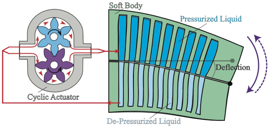
There are different ways to acuate a soft robot which include: pneumatic, photosensitive, combustion driven etc. In this week I am going to try out pneumatic actuation. When air is pumped into theses cavities, the cavities expand and the structure changes its shape. The structure can also change its shape when air is pulled out of these cavities. is kind of cool animal to biomimic and I think it would be great experiment. The cavities will swell up when air is pumped throught the air in and the whole body bends. The cavies can be desined according the the required shape and size that5 we need to move/bend the body.
Designing the Soft Robot
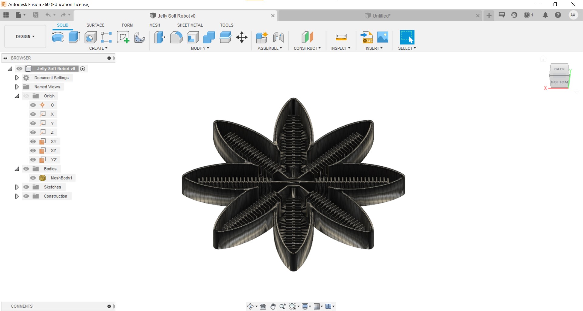
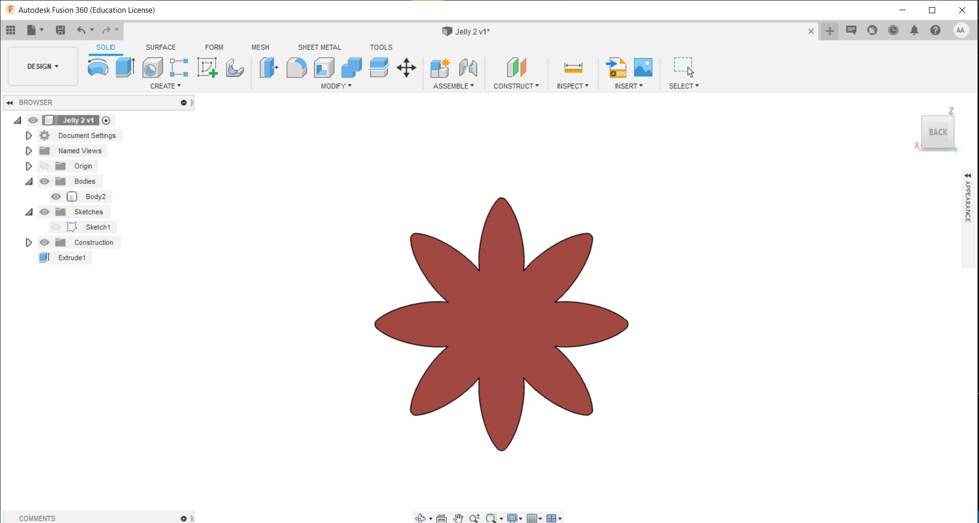
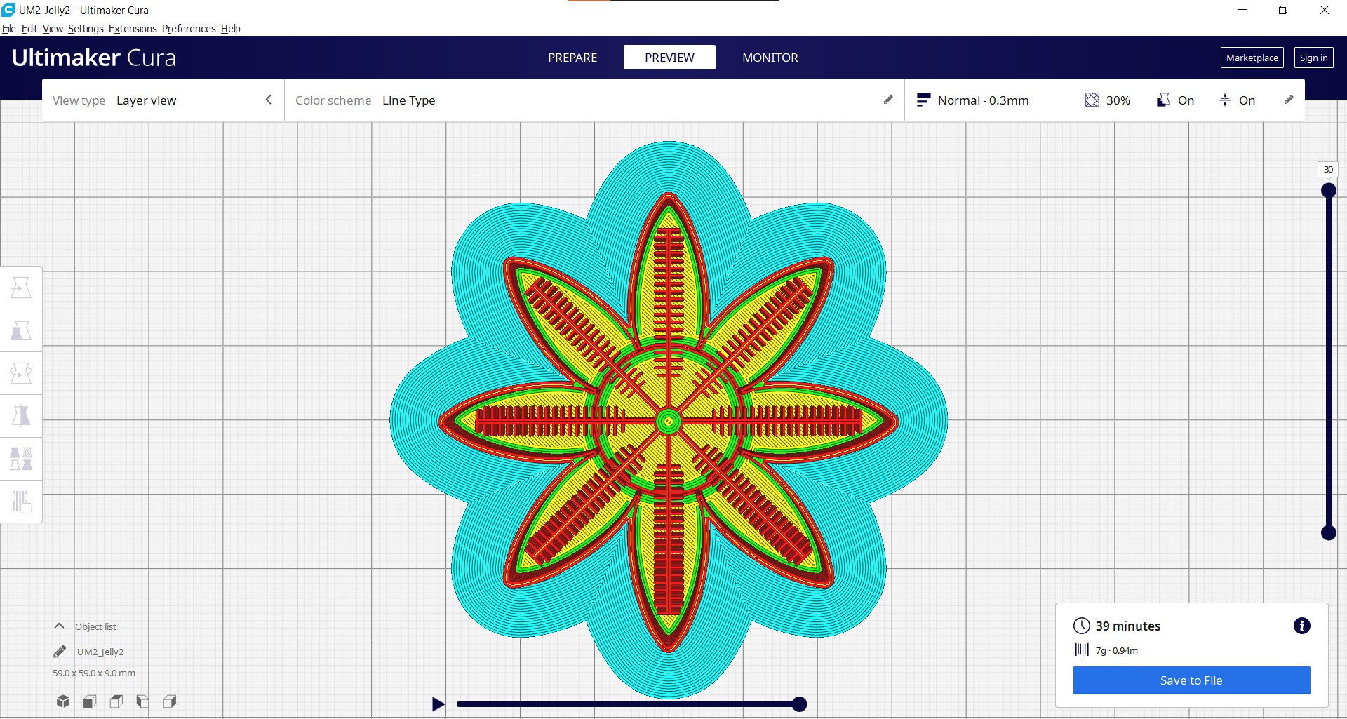
I am using Fusion 360 to design the 8 legged Jelly fish and for that I need to first create the negetive mold. In addition to basic frame, small pockets must be created along the length of fingers inside the mold so that air can be filled which causes the fingers to bend. The rib width was selected as 4mm and the length and breadth of the model is 6 cm * 6 cm with height of 9 mm.
Once the design is completed the next step is to export the model as STL for 3D Printing. Here I had used 3D printing instead of milling since I want to save time and 3D printed molds are more accurate than the latter. Next the STL file added to Cura and is sliced based on requirements.
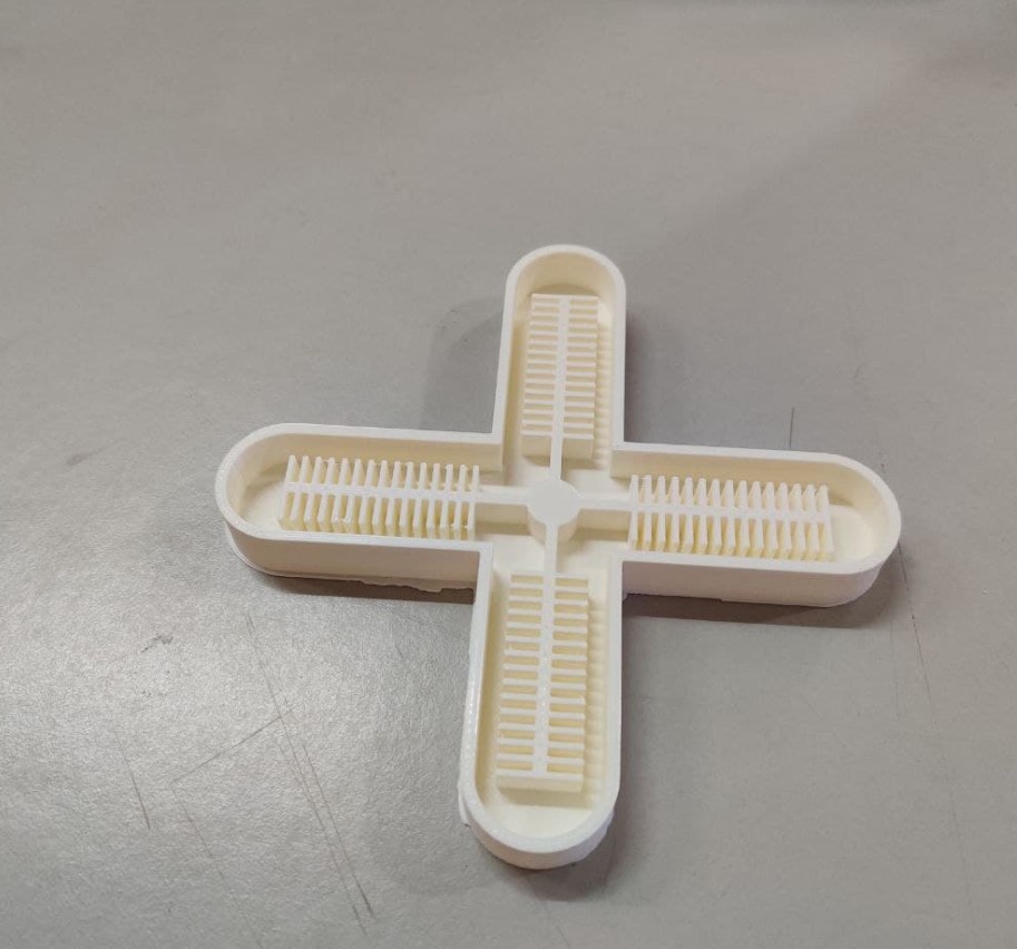
The next step is to 3D print the negetive mold using Ultimaker which I will complete once the lab reopens. The below image shows the 3D printed mold which contains the top and the bottom part. I had purposefully reduced the height of the top part to impart flexibility to the silicon mold. I had also provided a central cavity which fits the connector that I have so that I could inflate the gripper without air leakage.

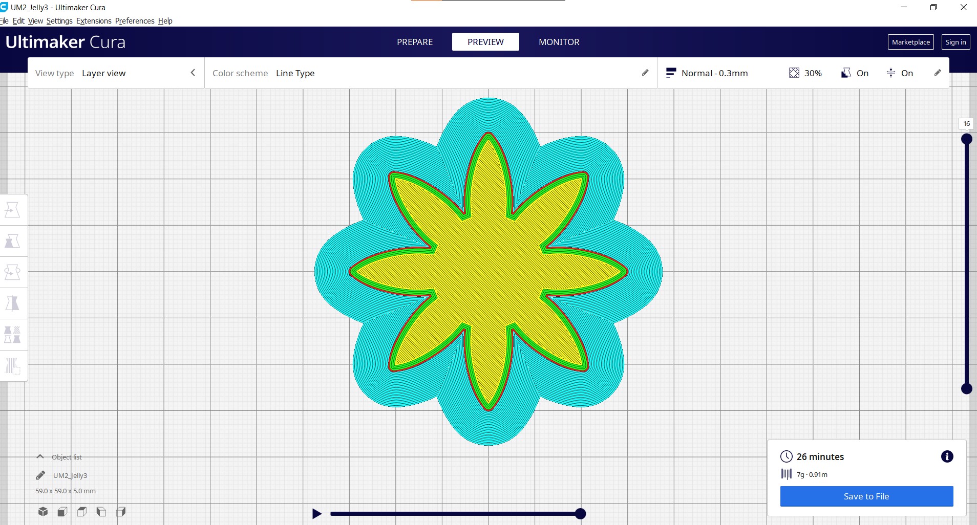
I had also 3D printed a soft robotic gripper with different shape along with this as a Plan B, so that if the jellyfish doesn't work, I could use this to save time.
Casting
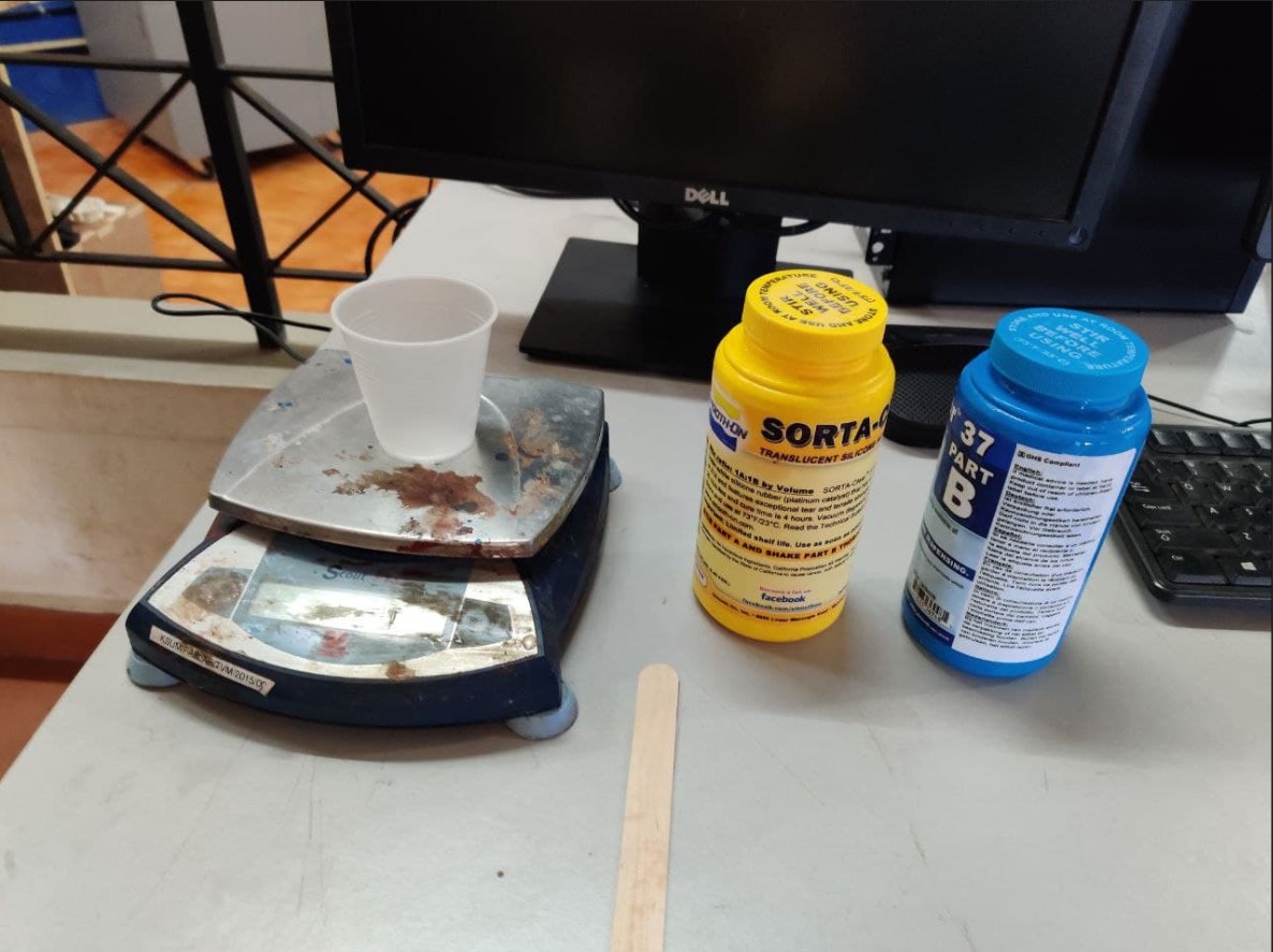
For silicon casting, I had used Smooth-On SORTA-Clear™ 37 silicone rubber which was available in the lab. SORTA-Clear™ Series rubbers are premium water white translucent silicone rubbers (platinum catalyst) which cure at room temperature with negligible shrinkage. Sorta Clear 37 has Shore 37A hardness and features high tensile and tear strength. This product also offers the convenience of a 1A:1B by volume mix ratio. SORTA Clear™ 37 silicone rubber is FOOD SAFE and can be used for culinary applications including casting chocolate and other confections.
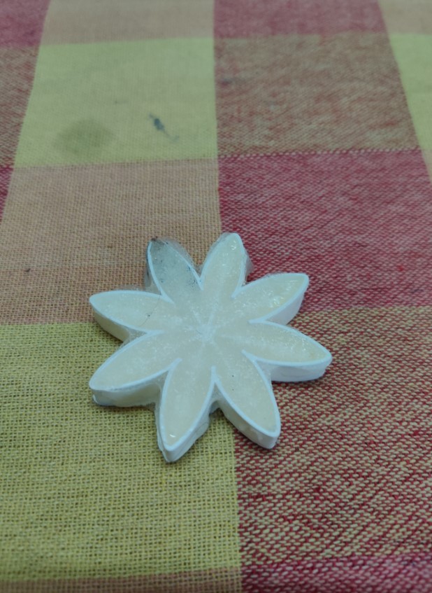
The next step is to mix the Part A and B, here I had used 10g of Part A and 10g of Part B and had mixed no so throoughly. Then I pored the mixture in the mold and waited for 4 long hours to solidify. Here comes the begining of all the errors that I had done. The mixture was not throoughly mixed which prevented the mold from solidification even after 12 hours. Furthermore, the silicon cast was very difficult to remove the mold due to it's small size. The image shown below depicts the errors that I had made:
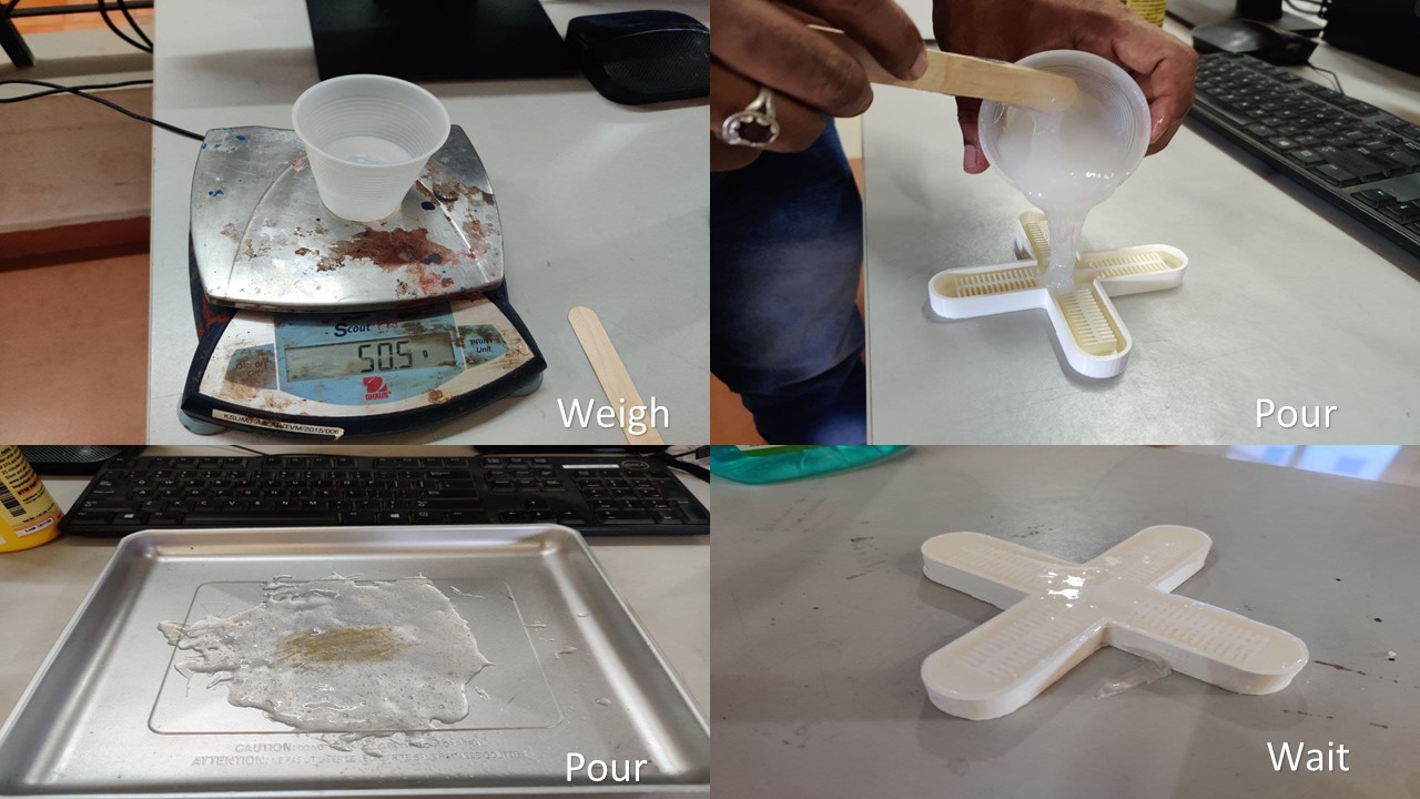
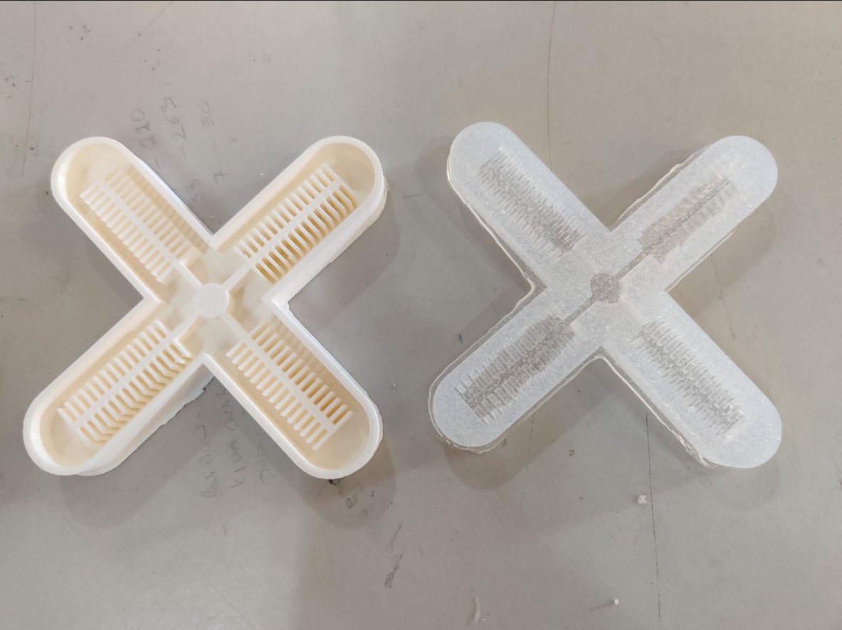
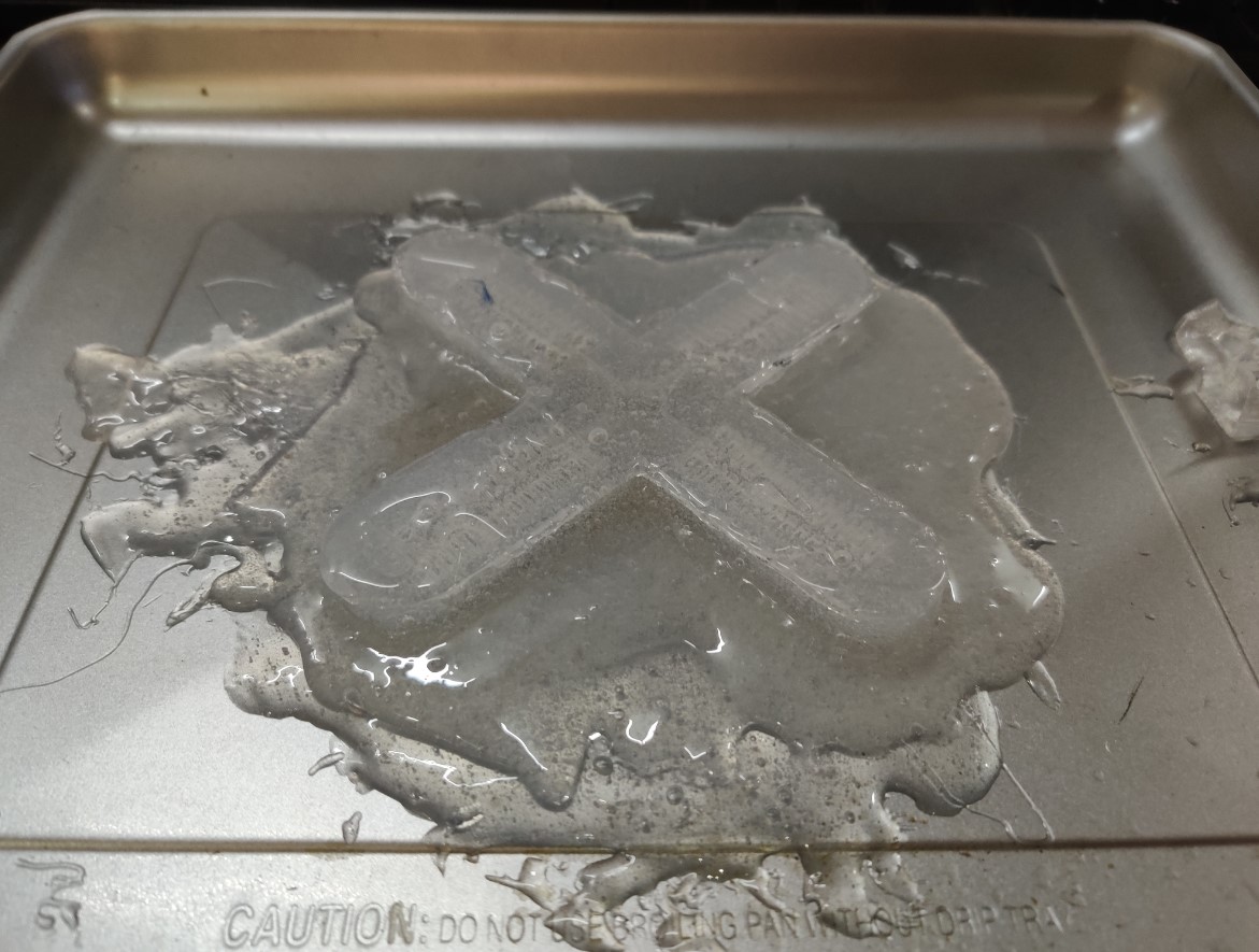
As, I had previously 3D printed the mold of soft robotic gripper, the transitition was seamless. For this mold, I had used 25g of Part A and 25g of Part B, with the help of my instructor, I had throoughly mixed the parts this time and had poured to the mold and waited for 4 straight hours to solify. I had also poured some extra silicon in an oven plate to seal the bottom part of the negetive mold. The silicon poured on the plate when solified will be jointed to the bottom half using the same silicon material.
After 4 hour long wait, I had removed the silicon rubber from the mold. The mold came out perfectly, thanks to the bigger footprint of the mold. The next step is stick the bottom side of the mold to the cured silicon poured into the oven plate using silicon. In this step I need to ensure that there is no gap in the edges and the alignment has to be perfect.
The next step is to attach the bottom side of the silicon rubber to the cured rubber poured on the surface of the oven plate. The parts are sticked together using silicon rubber and again left for it to cure. Once the parts are cured the extra silicon from the edges are removed using a cutter ensuring that there is no air leakage.
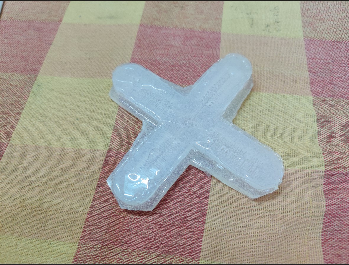
The below image shows the sealed soft robotic arm.
The next and the final step is to test the soft robotic device that I had made. For that salvaged some medical parts like a tube, connector and BP monitor bulb from my father's itenary (He is a doctor, by the way). I initally tried pumping with the bulb but it didn't work as the pressure was too low.
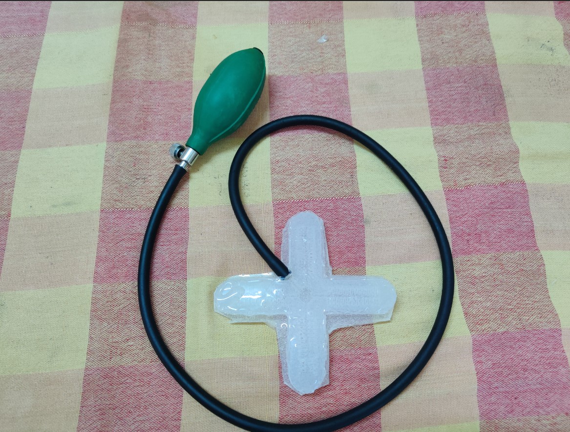
So to test the outcome, I had connected the tube to a compressor available in the Fab Lab to supply the air and this is what I had observed:
Result
I didn't get the result as expected due to the silly mistakes that I had made during the fabrication. The following are the errors that I had made:
- I had unncessarily increased the thickness of bottom layer which prevented the silicon to flex as expected
- The air cavities got filled by silicon thereby reducing the volume taken by air, thereby reducing the efficiency